Categories
Fab Academy AS220 - Providence, RI Fab Academy Providence -Year II - Teaching

FabRC – Final Project Planning

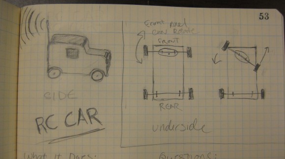
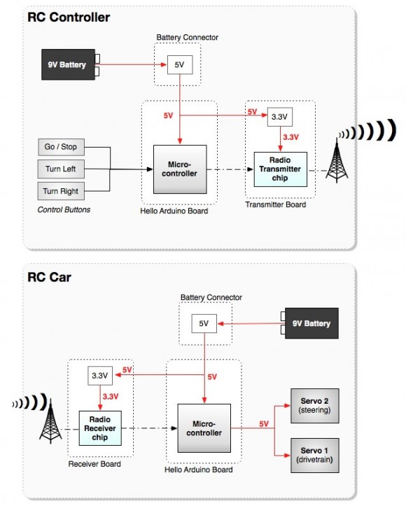
This week at Fab Academy we are planning our final projects.  I am creating a digitally fabricated RC car.  First I defined my all the system components, how they would interact with each other and what the logic / voltage levels needed to be throughout that system.

Logic Levels / Radio – Functional Block Diagram

What Will It Do?

  • Drive forward / stop
  • Turn left / right
  • Use radios to control the car wirelessly.

Who’s Done What Beforehand?

  • David Mellis made pressfit cars – this one needs to be more of an enclosure to house the electronics
  • JeeLabs: http://jeelabs.org/ has created some code and designs that I plan to modify and use with the Hope RF radios.

What Materials and Components Will Be Required?

  • 2 servos
  • 2 radio boards (utilizing the Hope RF radios)
  • 1 or 2 Arduino boards (hello Arduino boards)
  • Masionite
  • LEDs (possible decoritive addition)
  • Acrylic (possible decoritive addition)
  • Possibly plastic to cast parts (possible decoritive addition)
  • Metal rods for axels?
  • copper-clad PCB stock
  • Various components already in the inventory

How Much Will It Cost?

  • $0 – $20 Most parts already in the inventory.
  • Need to purchase Hope RF radios – $12.00 for a pair.
  • Need to purchase a few additional non-standard, non-inventory components from Digikey ($10.00 + shipping).

What Parts and Systems Will Be Made?

  • Connect the radio boards to the Arduino
  • Figure out how to issue commands to control the car
  • Turn lights on and off

What Processes Will Be Used?

  • Laser-cut press fit for the car body (possibly being replaced by molded shell / parts)
  • Milled circuit boards.
  • Molded parts for wheels / accessories

What Tasks Need to Be Completed?

  • Need to investigate how to get the boards to talk to each other.
  • Control with computer keys at first.
  • Would like to eventually add a wireless joystitck control box.

What Is The Schedule?

  • This Week –> Design the car and investigate the how to talk to the radios
  • Next Week –> Troubleshoot the project, work on the control structure.

How Will It Be Evaluated?

  • Can the radios talk to each other?
  • Do the controls work?
Categories
Fab Academy AS220 - Providence, RI Fab Academy Providence -Year II - Teaching

Pure Data to Arduino Over Serial

For Fab Academy, Shawn Wallace put together a basic example of getting the Arduino to make music using Pure Data.

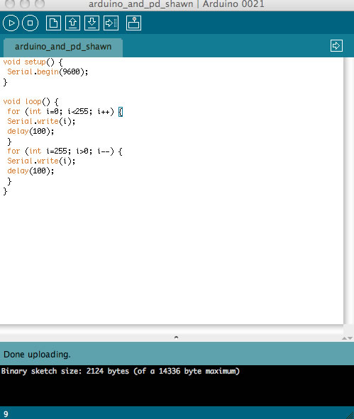
  • Next, flash your Arduino with the following code:
void setup() {
 Serial.begin(9600);
}

void loop() {
 for (int i=0; i<255; i++) {
 Serial.write(i);
 delay(100);
 }
 for (int i=255; i>0; i--) {
 Serial.write(i);
 delay(100);
 }
}

pde

  • Then, save this Pure Data patch to a text file, name it SimpleExample.pd, and open it up in Pure Data:
#N canvas 644 73 523 614 10;
#X obj 186 309 dac~;
#X obj 110 182 r left;
#X obj 298 180 r right;
#X obj 36 150 osc~;
#X obj 80 151 osc~;
#X obj 39 194 *~ 0.2;
#X obj 235 181 *~ 0.2;
#X obj 266 227 *~ 1;
#X obj 90 226 *~ 1;
#X obj 35 47 comport 9600;
#X msg 36 17 devices;
#X msg 95 19 open 2;
#X floatatom 35 70 5 0 0 0 - - -;
#X obj 35 102 * 10;
#X obj 75 103 * 20;
#X connect 1 0 8 1;
#X connect 2 0 7 1;
#X connect 3 0 5 0;
#X connect 4 0 6 0;
#X connect 5 0 8 0;
#X connect 6 0 7 0;
#X connect 7 0 0 1;
#X connect 8 0 0 0;
#X connect 9 0 12 0;
#X connect 10 0 9 0;
#X connect 11 0 9 0;
#X connect 12 0 13 0;
#X connect 12 0 14 0;
#X connect 13 0 3 0;
#X connect 14 0 4 0;

A nice feature of Pd is that all the patches are in a simple text format.

To Get this Example Working:

  • Open Pure Data
  • Open the “SimpleExample.pd” file in Pure Data
  • Click on the “devices” message box: This will list any available serial ports in a numbered list.
  • On my Mac, the usb port connected to the microcontroller was on port 2; (it may be different on your computer)
  • Find the correct port number and change the “open” message from “open 2” to “open (your port # here)”. To do that, enter Edit mode under the Edit menu. Now you can type directly into the message boxes. After you change the “open” message, leave edit mode and do the following:
  • 1. Select “compute audio” in the main Pd window
  • 2. Click on the “open” message to open the serial connection

pd

You should see output of the comport changing, and should hear a rising and falling tone.

Categories
Fab Academy AS220 - Providence, RI Fab Academy Providence -Year II - Teaching

Hello (Make Your Own) Arduino

arduino
For reasons I haven’t uncovered yet, I was unable to use the Arduino IDE to burn the bootloader to a fabbed Arduino board. For my first attempt at this, see the Fabkit / Fabduino post. Also see Ed Baafi’s Fabkit / Fabduino page for how to program an fabbed Arduino without an external clock through the Arduino IDE. In both OS X and Ubuntu I was unable to connect to the board through the IDE. Shawn Wallace suggested that I use the following code. (See “To Program Your Arduino” section below) The code below worked for me in Ubuntu. NOTE: This code below works for a using an external 8MHZ resonator, see the links to the .png files.

Download the Files

Download Files to Mill
Get the files from the Fab Academy site
Download the Arduino Bootloader File for the Atmega168
Right click to save the files

To Program Your Arduino:

Set the fuses with:

Paste code is all in one line

avrdude -c usbtiny -p m168 -B 5 -u -U lock:w:0x0F:m -U  efuse:w:0x00:m -U
hfuse:w:0xdd:m -U lfuse:w:0xf6:m -P usb

Burn the bootloader with:

Paste code is all in one line

avrdude -P usb -c usbtiny -p m168  -u -U flash:w:ATmegaBOOT_168_pro_8MHz.hex
-U lock:w:0x0F:m -B .2

The options used:

  1. -u –> Disable safemode, default when running from a script.
  2. -U :r|w|v:[:format] –> Memory operation specification. Multiple -U options are allowed, each request is performed in the order specified.
Categories
Fab Academy AS220 - Providence, RI Fab Academy Providence -Year II - Teaching

FabKit / Fabduino

fabduino
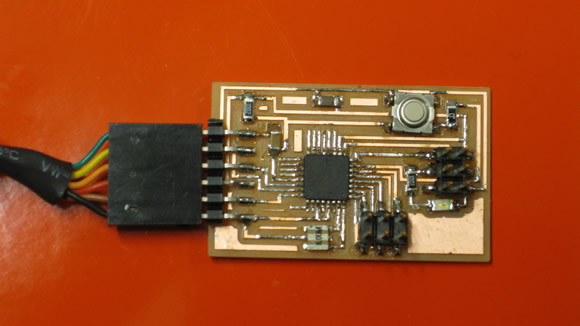
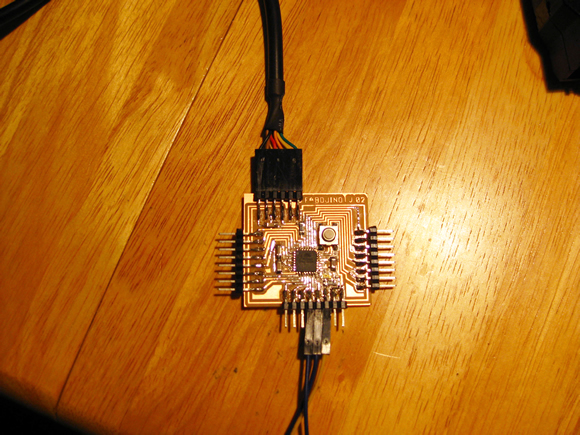
I milled and stuffed Ed Baafi’s Fabduino board version 2. I am still troubleshooting the board, but I may just start over. So far avrdude cannot talk to the chip to burn the bootloader. I have tried the USBtiny and the ATAVRISP2, but I did not have any luck with either one.

I have also tried using just avrdude and the Arduino IDE without success. I have also tried every possible configuration of FTDI plus jumpers to the ISP. (As well as just jumpers to the ISP). I will likely start over, perhaps I overlooked a trace when I was editing the .png file – see “other issues” below.

Error Message (both avrdude and Arduino IDE):

avrdude: initialization failed, rc=-1
Double check connections and try again, or use -F to override this check.

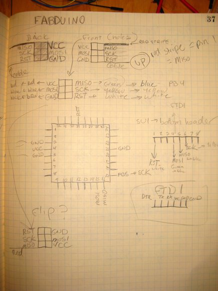
Figuring Out the Pin to Microcontroller Setup:

The Fabduino does not have a 6-pin header, so it needs to be programmed using jumpers attached to the pins that would be on the programming header.

fabduino

Other Issues:

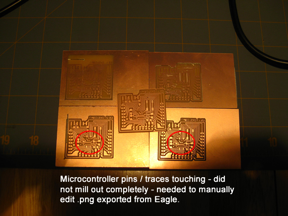
I milled this board several times. When I exported the file as a .png from the origional Eagle board file, there were some jagged edges that caused the toolpath around the microcontroller pins to remain connected. At first I thought that this was due to the Fab modules settings or the bit size. I later figured out that if I cleaned up the problem areas in the .png manually in The Gimp, the toolpath issues went away.

fabduino