Categories
16 Digital Fabrication Project Development Fab Academy AS220 - Providence, RI Fab Academy Final Project Fab Academy Providence -Year I - Student Projects

Fab Academy Final Project Proposal – Puppet Master Universal Remote

puppetmaster

Final Project Overview

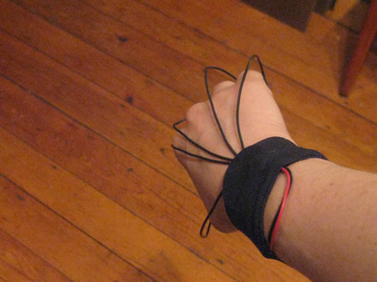
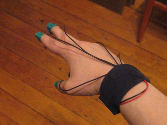
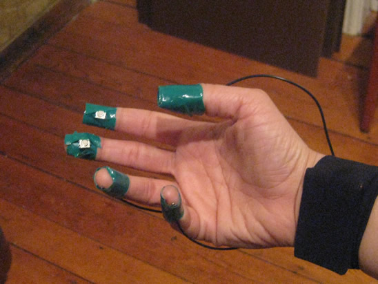
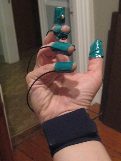
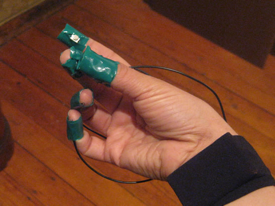
My final project for Fab Academy is a universal remote I am calling PuppetMaster, due to its ability to wirelessly control out of reach objects / devices using the fingers. This device enables the user to remotely control infrared receiving devices (such as a television or stereo) from a maximum distance of 100 – 150 feet. The user of PuppetMaster will be able to operate the remote by using switches embedded in the fingertips. The board and power supply will be worn around the wrist like a watch or bracelet. (This makes weight and a small form factor a major design consideration for this project). Additional controls will be added in later stages. (see details below)

Form Factor / General Idea Mockup

If IR model – Infrared LED would be placed on top of hand in wrist strap.

puppetmasterpuppetmasterpuppetmaster

I intend to fab the boards myself, using the standard fab inventory parts with a few exceptions, (especially the sensors used in the later stages). The first stage (to be completed by June 1 for the fab academy final project) consists of one mode of control (IR) but other modes (radio, bluetooth and additional gestural sensors) will be added as the project progresses. (See stages outlined below.) A dial or switching mechanism will be added to switch between the modes. These additional modes (combined with the necessary code) will allow the user to control almost any device with hand gestures. I am also keen to develop a gestural language in tandem with the addition of 6-axis sensors (3 axis gyro, 3 axis accelerometer) to the device.

Standing On The Shoulders of Giants – What I Will Borrow

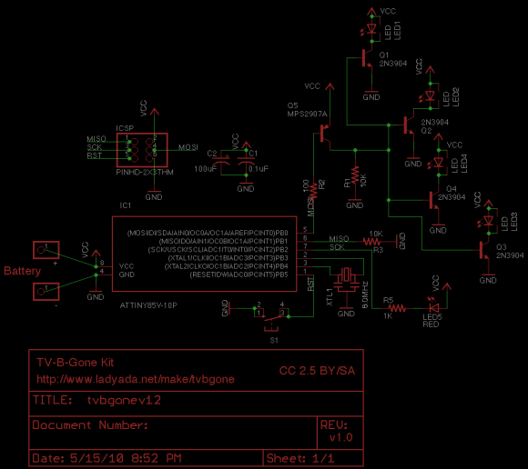
I intend to stand on the shoulders of giants for the first stage (infrared) of this project. The IR transmitter portion of this project is based on Mitch Altman‘s popular TV-Be-Gone device – as modified to transmit 150 feet by Lady Ada.

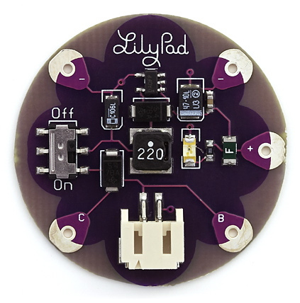
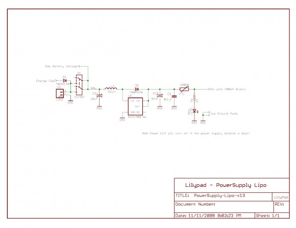
I intend to use a lithium battery for lighter weight and longer life – that power supply will be based on the LiPower design by Leah Buechley, but I intend to make mine slightly smaller.

Overall Project Goals:

  • Create a remote control that takes input from finger movements / gestures
  • Remote is small and wearable (will likely look like a bracelet or a watch) with connections to the fingertips.
  • Remote is comfortable enough for long-term wear, will help to relieve hand / joint fatigue

Short Term Goals By Stage

Prototype in stages, adding functionality and additional control channels / technologies in each stage

1.0 Stage 1: Infrared

1.1. Use infrared to turn off on devices, navigate devices (most likely television)

1.1.1. Most likely commands:

1.1.1.1.On

1.1.1.2.Off

1.1.1.3.Up channel

1.1.1.4.Down channel

1.1.1.5.Other specialty features?

1.2. Power supply -> LiPo model uses lightweight lithium battery and outputs 5V

1.2.1 This is perfect for the TV-B-Gone style board I want to create / modify / fab

1.3 Parts List for puppetmaster (phase 1 – IR)

1.4. Complete working prototype by 6/01/2010

2.0 Stage 2: Radio Control

2.1. Add radio control to Stage 1 prototype

2.2. Enable mode switching on input device different modes different gestures

2.3. Experiment with driving a RC device.

2.4. Complete working prototype by 6/30/2010

3.0 Stage 3: Bluetooth

3.1. Add Bluetooth to Stage 1 prototype

3.2. Enable mode switching on input device different modes different gestures

3.3. Experiment with driving a RC device.

3.4. Complete working prototype by 7/30/2010

4.0 Stage 4: 6-axis motion sensors

4.1. Add additional sensors to interface:

4.1.1. 6-axis motion sensors (3 axis gyro, 3 axis accelerometer) to input gestures.

4.2. Complete working prototype by 11/01/2010

5.0 Stage 5: Gestural Language

5.1. Utilize 6-axis motion sensors (3 axis gyro, 3 axis accelerometer) to input gestures.

5.2. Creation of full blown gestural language (possibly based on sign language)

5.3. Complete working prototype by 11/01/2010

6.0 Stage 6: Personal LAN

6.1. Connect to the internet to create personal LAN.

6.1.1. Most likely by fabbing a board that can plug into an iphone,

6.1.2. This board could then provide any other user devices with data access

6.1.3. Could connect to Premonition system

6.2. Complete working prototype by 11/01/2010

Schedule:

Stage Description Deliverable Date Range
1.0 Infrared Working infrared remote prototype 05/16/2010 06/01/2010
2.0 Radio Control Working infrared remote prototype + radio control 06/01/2010 – 06/30/2010
3.0 Bluetooth Working infrared remote prototype + radio control + bluetooth 07/01/2010 7/30/2010
4.0 6-axis Sensors (gyro, acelorometer) Stages 1 or 2 plus working sensor prototype 06/01/2010 11/01/2010
5.0 Gestural Language Gestural language mapped to the 6-axis sensors 06/01/2010

11/01/2010

6.0 Personal LAN Local area network driven by iphone data access that can wirelessly provide data to other personal devices. 08/01/2010

11/01/2010

Distribution Plan

I plan to distribute this project through my website as downloadable schematics and board files. Releases will be made available as individual stages are completed. If the project becomes popular, I may consider distributing it as a kit.

It is unlikely that I will patent this device, as patents are expensive and afford little protection unless you are the owner of a large company with deep pockets who is prepared to litigate.

I instead intend to use the Creative Commons for both licensing and enabling others to find these plans. (a non-commercial – modifications allowed – share alike license seems to make the most sense). This will enable me to keep the copyright to my work while allowing others to us, modify and improve it.
Categories
11 Interface & Application Programming Fab Academy AS220 - Providence, RI

Using a GUI to Control Processing Output with ControlIP5, Firmata via Serial

The Fab Academy Assignment

  • Write a user interface for an input &/or output device

I created this simple interface to control turning on and off an LED that is attached to a microcontroller via the serial port on my Mac. I wanted to see if I could get the ControlIP5 (used to create the GUI), Firmata and serial libraries working together before I tried using more complex hardware. I intend to experiment with driving multiple servos and possibly tinkering with bluetooth using the NXT library as an “cheap” way (it’s “cheap” because I already own the Mindstorms hardware) to play around with bluetooth without buying additional bluetooth modules.

The Interface: Default / Initial State:

The interface is simple – the Turn On button turns the light on and the Turn Off button turns it off.

Here’s the Processing code:

/*-------------------------------------------------------------------
 * Fab Academy -- Module 09: Interface Programming
 *--------------------------------------------------------------------
 * Assignment: Write a user interface for an input &/or output
 * device.
 *--------------------------------------------------------------------
 * Purpose:  This program is a test to get the controlIP5, Firmata,
 * and serial libraries working together through the serial port.
 * This program uses a simple button GUI interface to turn on / of an
 * LED.
 *--------------------------------------------------------------------
 * Anna Kaziunas France - 30 March 2010
 * Combined / Modified example code from:
 * controlIP5 buttons example (included the library download)
 *------------------------------------------------------------------*/

import processing.serial.*;
import cc.arduino.*;
import controlP5.*;

ControlP5 controlP5;
// we have to use controlP5.Button here since there
// would be a conflict if we only use Button to declare button b.
controlP5.Button b;
Arduino arduino;

// Variables
int ledPin = 11;
int buttonValue = 0;
int myColor = color(0);

void setup() {
  arduino = new Arduino(this, Arduino.list()[2], 57600);
  arduino.pinMode(ledPin, Arduino.OUTPUT);
  size(640,480);
  smooth();
  frameRate(30);
  controlP5 = new ControlP5(this);
  controlP5.addButton("Turn_On",255,200,80,100,70);
  controlP5.addButton("Turn_Off",0,200,160,100,70);
  println(Arduino.list());
}

void draw()
{
  background(myColor);
  fill(buttonValue);
  rect(20,20,width-40,height-40);
}

public void controlEvent(ControlEvent theEvent) {
  println(theEvent.controller().name());

}

// function buttonA will receive changes from
// controller with name Turn_On
public void Turn_On(int theValue) {
  println("a button event from Turn_On: "+theValue);
  myColor = theValue;
  arduino.digitalWrite(ledPin, Arduino.HIGH);
}

// function buttonB will receive changes from
// controller with name Turn_Off
public void Turn_Off(int theValue) {
  println("a button event from Turn_Off: "+theValue);
  myColor = theValue;
  arduino.digitalWrite(ledPin, Arduino.LOW);
}

Skills Learned

  • I learned how to find, utilize and manipulate additional Processing libraries that enabled me to create a simple user interface from a computer to a physical object (LED).

Tools Used

  • Processing, ControlIP5 & Firmata libraries
  • Arduino ATTMega, LED
Categories
04 Electronics Design and Production Fab Academy AS220 - Providence, RI Fab Academy Providence -Year I - Student Projects

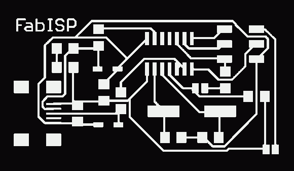
Fab ISP Part I: Milling Out The Board

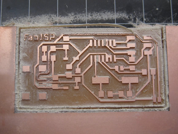
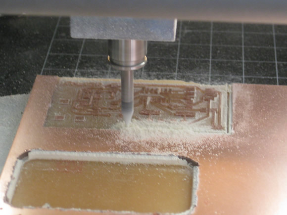
Today I milled out my first PCB on the Modela. Technically it is not a “printed circuit board”, but machined out of copper-clad PCB stock.

milling board

Fab Academy Assignment

The assignment is to design a circuit board, mill it, and program it in assembly language. This post documents Part 1 of this process which entails:

  • Designing the board (For this board I used the already created Fab ISP board file – I plan to design a board for a later project).
  • Machining the board

Part 2 will document the process of putting the components into the board. Each student had to become acquainted with the following work flow:

  • Stuffing components
  • Programming

The first step in making a board is to create a tool path to send to the machine:

To Mill the Board:

  • Import a PNG image into cad.py.
  • Create the tool path in cad.py
  • Send to the Modella

Fab ISB

To Cut through the Board:

  • Import the border PNG image into cad.py
  • Create the tool path in cad.py
  • Send to the Modella

Border

Categories
10 Sensors, Actuators and Displays Arduino / Processing Fab Academy AS220 - Providence, RI Halloween

Motion Sensing Glow Skull

Voodoo Glow Skull

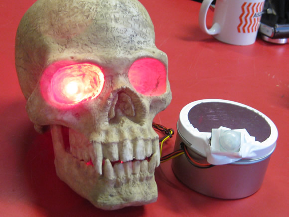
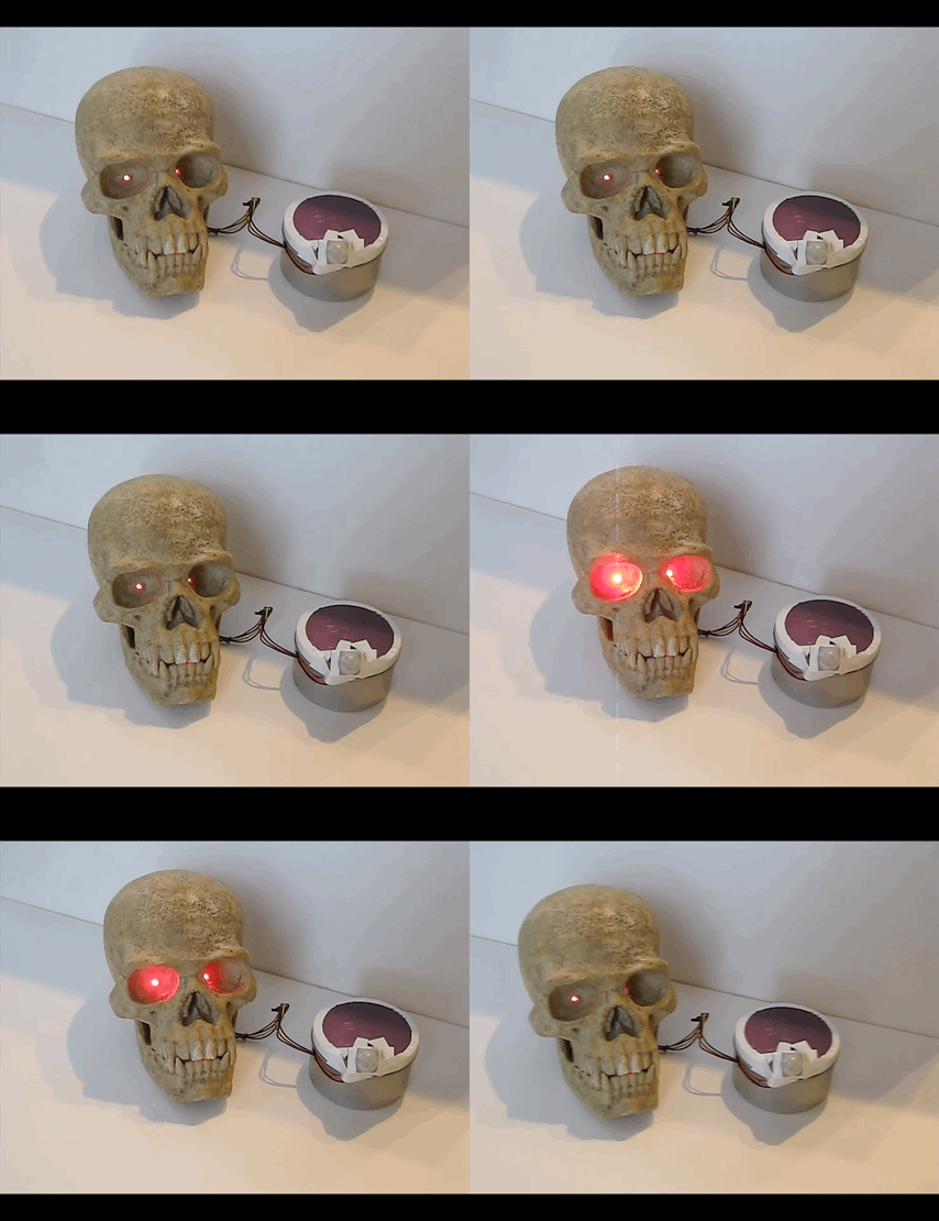
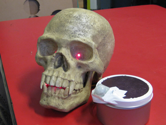
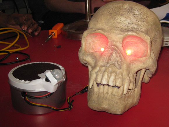
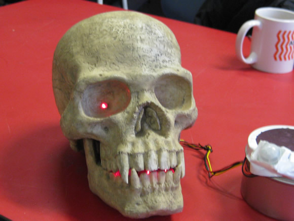
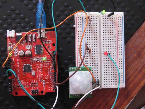
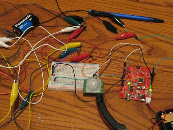
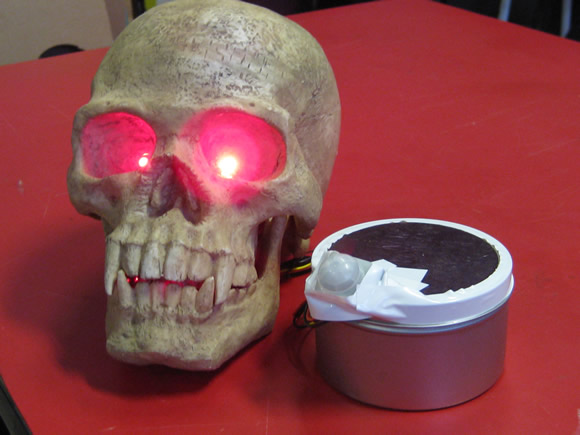
I am ready for Halloween early this year. For my I/O sensor project for Fab Academy I put together a Arduino-controlled motion sensing glowing skull. When motion is detected by the parallax motion sensor, the board turns on the LEDs in the mouth and fades in and out the LEDs glued into the eye sockets.

The Fab Academy Assignment

  • Interface an input device with an output device.

The Project: Motion Sensing Glowing Skull

Voodoo Glow SkullVoodoo Glow Skull

Parts List:

  • 1 Parallax PIR [Pyroelectric (“Passive”) InfraRed)] motion sensor
  • A few lengths of wire
  • 1 Arduino compatible board (I used a Seeduino (Seeed Studios) I had laying around). I like this board because I can flip the power source switch to turn it off / on.
  • 1 9 volt battery
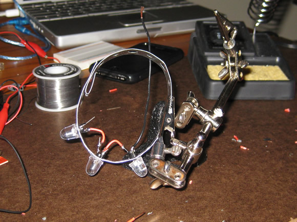
  • Mouth: 10mm Red LED (3)
  • Eyes: 5mm Red Wide-Angle LED (2)
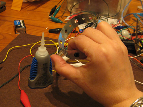
  • 5 in or so metal strip with holes (to house mouth LEDs
  • 3 plastic LED holders (to insulate the mouth LED wires from the metal strip)
  • super glue / hot glue

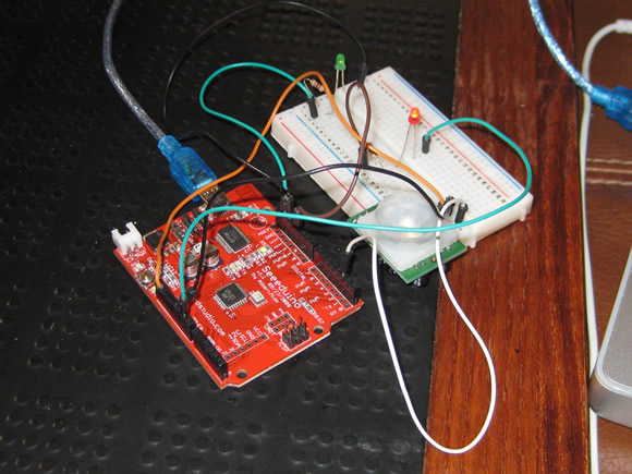
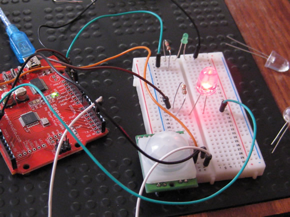
Prototyping the Circuit / Interaction + Putting It Together:

prototypingprototyping - jumbo LEDprototypingprototypingLED harnessLED harnessGlow!

Code:

The code works – but needs to be modified, right now after the motion is activated, the lights stay on / fade in and out in an infinite loop until the power is switched off. Look for an update to this post.

Arduino code for the LEDs and Parallax PIR Motion Sensor:

/* -----------------------------------------------------------------
 Anna Kaziunas France
 --------------------------------------------------------------------
 Fab Academy - Sensors I/O Module
 Glowing Skull Project
 03/02/2010
 --------------------------------------------------------------------
 Motion Sensor code:
 Motion Sensor code:I have seen this code a few places,
 it is never attributed to anyone in particular.
 I saw it last at: http://www.ladyada.net/learn/sensors/pir.html
 --------------------------------------------------------------------
 LED Fader code by: By David A. Mellis - Created 1 Nov 2008
 Modified 17 June 2009: By Tom Igoe
 http://arduino.cc/en/Tutorial/Fading
 --------------------------------------------------------------------
 Combined / Modified by Anna Kaziunas France - 03 March 2010
 --------------------------------------------------------------------

 --------------------------------------------------------------------
 Purpose of this Program
 --------------------------------------------------------------------
 Read input value from the sensor
 Determine if motion is present (input is HIGH)

 When motion is detected via motion sensor:
 1. Eyes slowly glow red (fade in and out - continue)
 2. Mouth glows (steady)

 When motion is not detected after (length of time)
 Switch off LEDs
 ------------------------------------------------------------------*/

// Variables
int ledPinSolid = 13; // choose the pin for the LED
int ledPinFade = 11; //
int inputPinSensor = 2; // choose the input pin (for PIR sensor)
int pirState = LOW; // we start, assuming no motion detected
int val = 0; // variable for reading the pin status

void setup() {
  pinMode(ledPinSolid, OUTPUT); // declare Solid LEDs as output
  pinMode(ledPinFade, OUTPUT); // declare Fader LEDs as output
  pinMode(inputPinSensor, INPUT); // declare sensor as input

  Serial.begin(9600);
}

// Begin Motion Detection
void loop() {
  val = digitalRead(inputPinSensor); // reading input value
  if (val == HIGH) { // if the input is HIGH
    digitalWrite(ledPinSolid, HIGH); // turn LED ON
    // sets the value (range from 0 to 255):
    analogWrite(ledPinFade, HIGH); // turn LED ON
    // fade in from min to max in increments of 5 points:
    for(int fadeValue = 0 ; fadeValue < = 255; fadeValue +=10) {
      // wait for 30 milliseconds to see the fade in effect
      delay(400);
    }
    // fade out from max to min in increments of 5 points:
    for(int fadeValue = 255 ; fadeValue >= 0; fadeValue -=10) {
      // sets the value (range from 0 to 255):
      analogWrite(ledPinFade, fadeValue);
      // wait for 10 milliseconds to see the dimming effect
      delay(110);
    }
    if (pirState == LOW) {
      // we have just turned on
      Serial.println("Motion detected Huzzah!");
      // We only want to print on the output change, not state
      pirState = HIGH;
    }
  }
  else {
    digitalWrite(ledPinFade, LOW); // turn Fader LEDs OFF
    digitalWrite(ledPinSolid, LOW); // turn Solid LEDs OFF
    if (pirState == HIGH) {
      // we have just turned of
      Serial.println("Motion ended");
      // We only want to print on the output change, not state
      pirState = LOW;
    }
  }
}

Skills Learned

  • Basic wiring
  • Modifing Arduino code
  • How to read a sensor datasheet

Tools Used

  • Arduino
  • Paralax motion sensor