Categories
08 Project Management 16 Digital Fabrication Project Development Fab Academy AS220 - Providence, RI Fab Academy Final Project Fab Academy Providence -Year I - Student Projects

Fab Academy Final Project Proposal [revised]: PuppetMaster

Puppetmaster Overview

My final project for Fab Academy is a universal remote I am calling PuppetMaster, due to its ability to control out of reach objects / devices using the fingers. This is the revised final project proposal – the first proposal was overly ambitious and encompassed too many sensor types in too short of a time period.

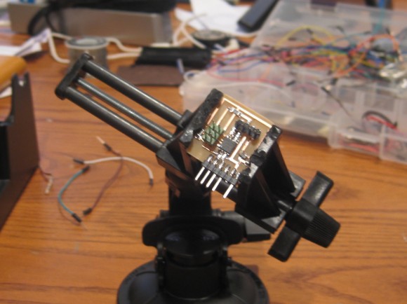
First Working Prototype: The first working prototype (illustrated in the PuppetMaster v.1-v.2 [capacitive sensing] post) uses thin copper sheets to create a capacitive sensor between the index finger and the thumb.

For Fab 6: By Fab Academy graduation I propose that PuppetMaster will consist of a fabbed board that reads gestural input from accelerometers.

Overall Project Goals / Design Considerations:

  • Create a remote control that takes input from finger movements / gestures
  • Remote is small and wearable (will likely look like a bracelet or a watch) with connections to the fingertips.
  • Remote is comfortable enough for long-term wear, will help to relieve hand / joint fatigue

Project Plan

Short Term Project Stages (Completed by Fab 6)

All board(s) will be fabbed, using the standard fab inventory parts with a few exceptions, (the sensors used in the later stages).

The First Stage [capacitive sensing]

  • Completed June 2nd – consists of using capacitive sensing as input data.

The Second Stage [ accelerometer input]

  • Completion before Fab 6 in August, will include the addition of accelerometer on each finger to record control gestures.
  • Simple gestures will be used for input controls.

Long Term Project Stages (Work in Progress – NOT for Fab 6)

  • Additional stages (to follow in the in the Fall) will include one mode of control (IR) but other modes (radio, bluetooth) will be added as the project progresses. (See stages outlined in the table below.)
  • Eventually, a dial or switching mechanism will be added to switch between the modes. Although the other modes of control mentioned above will be explored, the gestural input will be the primary focus.
  • In the final version of this prototype, the user of PuppetMaster will be able to input information via gestures and remote control objects by using sensors embedded in the fingertips.
  • These additional modes (combined with the necessary code) will allow the user to control almost any device with hand gestures. I also want to develop a complete gestural language (possibly based on sign language)in tandem with the addition of 6-axis sensors (3 axis gyro, 3 axis accelerometer) to the device.

Revised Project Schedule:

Stage Description Deliverable Date Range Board Version
Short Term – For Fab 6
1.0 Capacitive Sensing working capacitive sensing prototype Complete on 6/2/2010 v.1 – v.2
2.0 6-axis Sensors (gyro, accelerometer) accelerometer prototype 06/02/2010 – 09/16/2010 v.3 –
3.0 Basic gestural language A few mapable gestures that can be read by the computer / another device 06/02/2010 – 09/16/2010 v.3 –
Long Term – Future Improvements to make the remote “universal”
4.0 Infrared infrared remote prototype 05/16/2010 – TBD
5.0 Radio Control infrared remote prototype + radio control 07/01/2010 – TBD
6.0 Bluetooth infrared remote prototype + radio control + bluetooth 08/20/2010 – TBD
7.0 Complex gestural Language Full gestural language mapped to the 6-axis sensors 07/01/2010 –TBD
Categories
06 Embedded Programming Fab Academy AS220 - Providence, RI Fab Academy Providence -Year I - Student Projects

Hello Serial Echo

Fab Academy Module – 06 Embedded Programming


hello serial echohello serial echo

The Assignment

  1. read an AVR data sheet (ATTtiny 44) – COMPLETE
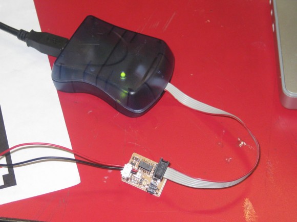
  2. make serial and programming cables – COMPLETE
  3. add (at least) a button to the serial echo hello-world board
  4. modify the serial echo assembly program to respond to the button
  5. modify the serial echo C program to respond to the button
  6. For more on items 3-5  –> See Modified Hello Echo – Part I: Hello Echo + Button + FTDI

The Project: Hello Serial Echo

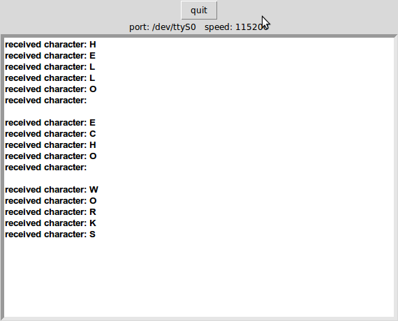
This hello world board uses a python program (term.py) to send keyboard input over a serial connection from the board to the computer. It is called “serial echo” because when the computer is able to communicate with the board via serial, the python program will allow the keyboard input to be sent to the board and then “echo” it back to the computer. The keyboard input / text will then appear in the python window.

Type the following into the terminal at the prompt:

python term.py /dev/ttyS0 115200

Where “/dev/ttyS0” is the name of the serial port connection to your computer.

When It Is Working – You Should See..

hello echo output

Skills Learned

  • I learned how to send data back and forth via a serial connection using Neil’s python program term.py.
  • Cable making

Tools Used

  • Modela milling machine
  • python – term.py
  • a computer with a serial connection
Categories
10 Sensors, Actuators and Displays Fab Academy AS220 - Providence, RI Fab Academy Providence -Year I - Student Projects

Hello Step Response FTDI

Hello Step Response

Step response board + FTDI + Capacitive sensing

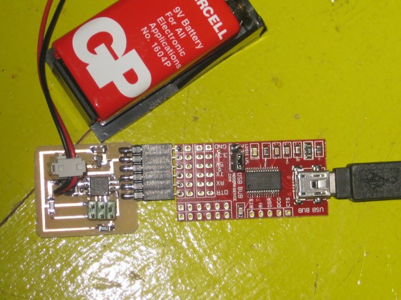
My first step in building this project was to start with the basics. I milled, stuffed and programmed the hello step response board (modified to use the FTDI header by Shawn Wallace). I have a Mac and I can’t troubleshoot / develop at home with the serial header examples.

What You Will See When The Example is Working:

I am using terminal in OS X 10.4.11  – this was the terminal command I used to run the hello step response example and what it will say when it can communicate with the board and begin plotting the graph.

Anna-Kaziunas-Computer:~/Desktop/fab_runs/step annakaziunas$
python hello.step.45.py /dev/tty.usbserial-A600dVDy
finding framing ...
start plotting
0

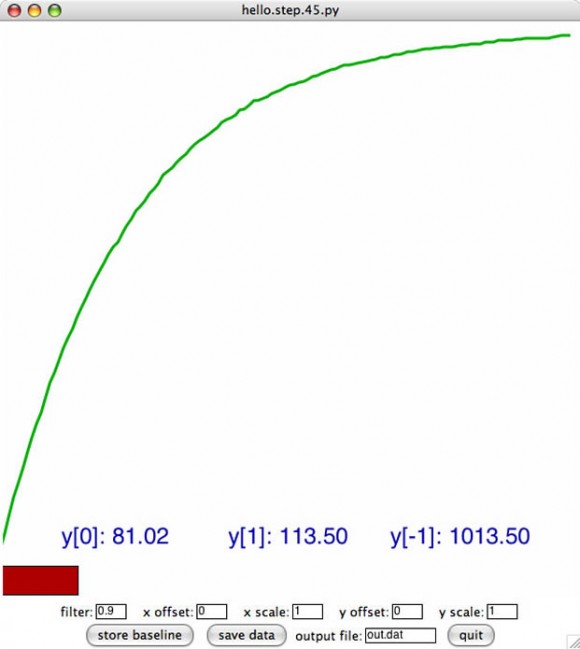
This is the graph that is displayed:

Here is a screenshot of the charging graph that is produced by Neil’s hello.step.45.py code.   This initial charging graph shows the capacitor charging up.

hello 44

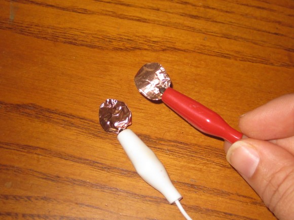
Here is the Capacitive Sensor I Made:

capacitive sensor

I used thin copper sheets to create the capacitor to test the hello step response board. I hooked them up to jumper wires.
When they copper sheets are touching or close to it, the graph will spike up. This indicates that current is flowing through the circuit.
When they are far apart the graph will flatten out. This indicates that the circuit is not connected.

For a video of this type of capacitive sensor in action – see the Puppet Master posts.

Categories
04 Electronics Design and Production Fab Academy AS220 - Providence, RI

FabISP Part II: Stuffing and Programming the Board


The Fab Academy Assignment
make and program a board

The Project: Fab ISP

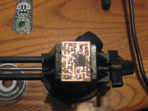
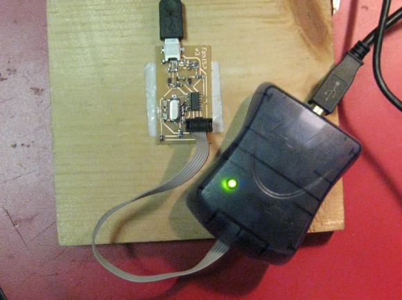
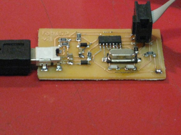
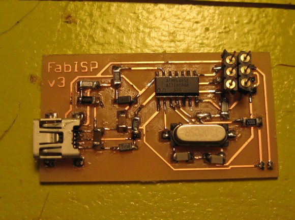
The FabISP was designed by David Mellis. It is an in-system programmer for AVR microcontrollers. Mellis designed it so that it could be produced in a Fab. It’s based on theUSBtiny andV-USB firmwares, allowing the ATtiny44 to communicate over the USB connection. It can be programmed with avrdude. See Mellis’s site for more details.

Skills Learned

This was my first board that I put together and programmed at Fab Academy

I learned how to:

  • mill a board
  • stuff a board
  • program a board
  • troubleshoot a board

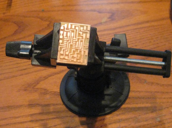
I had a alot of trouble initially with this board and I made at least 6 of these at various stages of completion before I got the final one working.
Some of the issues were due to my inexperience and need of practice with soldering and troubleshooting, but I discovered later that many of the problems were also due to the programmer I was using (see below).

Tools Used

  • ATMEL Mini AVR ATMEGA STK500 USB Programmer ISP (initially)
    • I had a lot of trouble with this programmer. I could not get it to green light on most of my boards – and when I did get a green light, it was unreliable. It would often go green – then yellow – then red. I would unplug it and then plug it back in and get flashing yellow or green.
    • I also wanted my own programmer to work with at home (the Ateml Mini belonged to the lab), so I purchased the very inexpensive USBtinyISP kit. This turned out to be a great solution. I occasionally have an issue with it heating up the boards a bit, but it doesn’t give me flaky results like the Atmel mini. Without the USBtinyISP, I would not have been able to complete any of the electronics / board related assignments with fabbed boards.
  • USBtinyISP AVR Programmer Kit
    • I found this programmer much easier to use than the Atmel Mini.
    • available from Adafruit Industries