Categories
04 Electronics Design and Production Fab Academy AS220 - Providence, RI Fab Academy Providence -Year I - Student Projects

Fab ISP Part I: Milling Out The Board

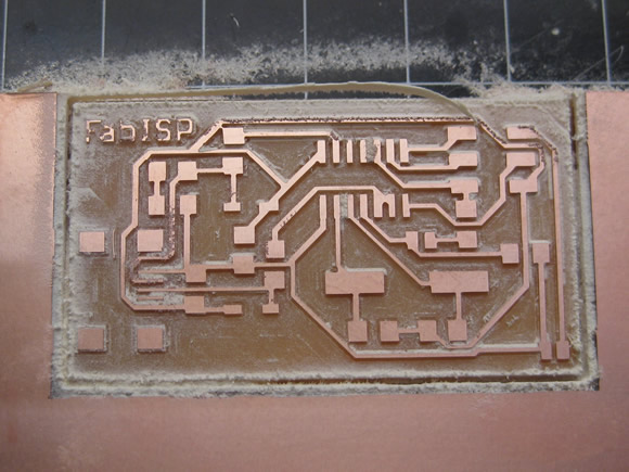
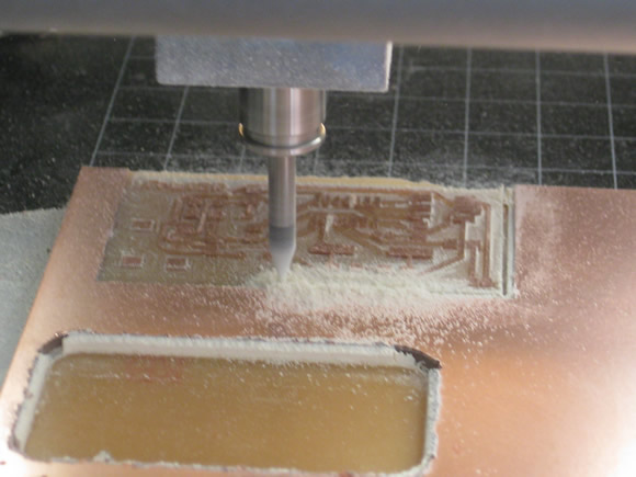
Today I milled out my first PCB on the Modela. Technically it is not a “printed circuit board”, but machined out of copper-clad PCB stock.

milling board

Fab Academy Assignment

The assignment is to design a circuit board, mill it, and program it in assembly language. This post documents Part 1 of this process which entails:

  • Designing the board (For this board I used the already created Fab ISP board file – I plan to design a board for a later project).
  • Machining the board

Part 2 will document the process of putting the components into the board. Each student had to become acquainted with the following work flow:

  • Stuffing components
  • Programming

The first step in making a board is to create a tool path to send to the machine:

To Mill the Board:

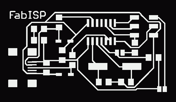
  • Import a PNG image into cad.py.
  • Create the tool path in cad.py
  • Send to the Modella

Fab ISB

To Cut through the Board:

  • Import the border PNG image into cad.py
  • Create the tool path in cad.py
  • Send to the Modella

Border

Categories
10 Sensors, Actuators and Displays Arduino / Processing Fab Academy AS220 - Providence, RI Halloween

Motion Sensing Glow Skull

Voodoo Glow Skull

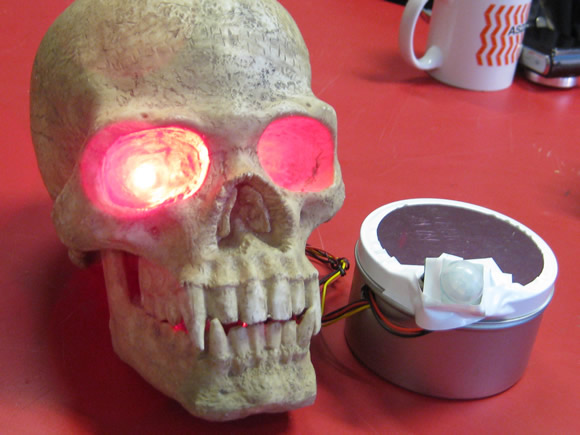
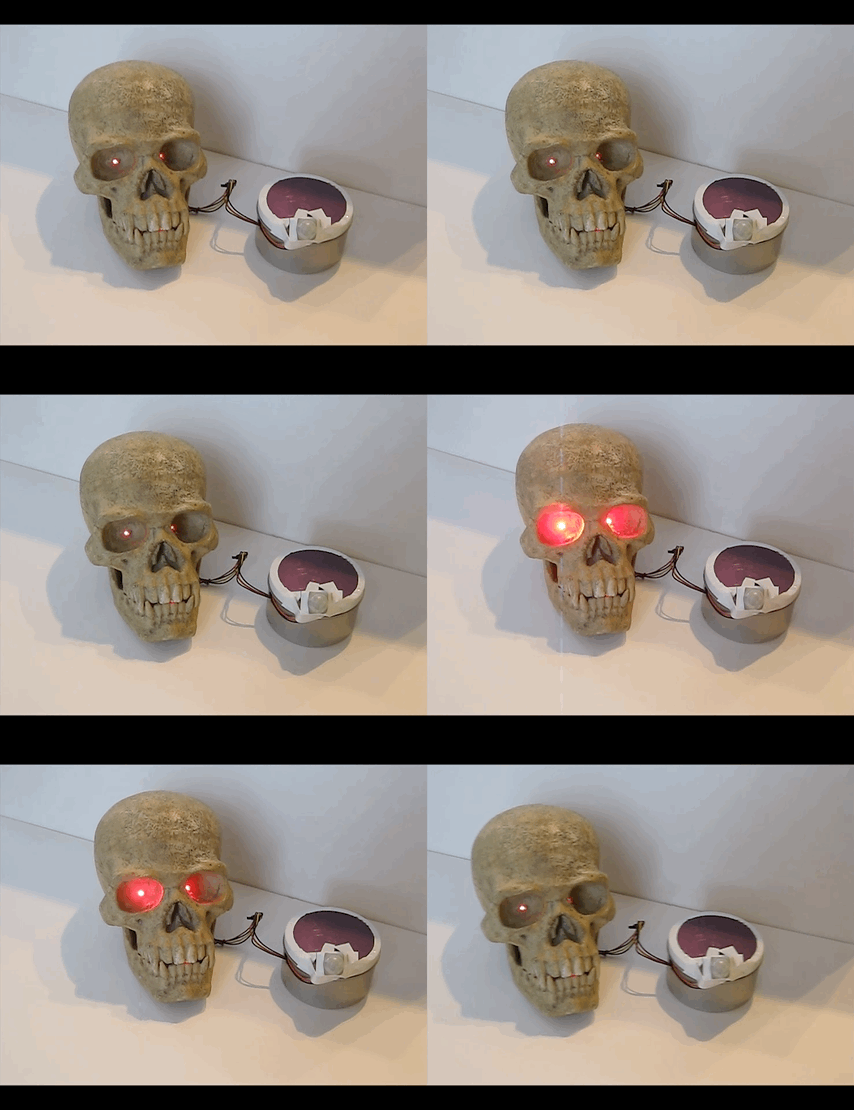
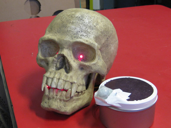
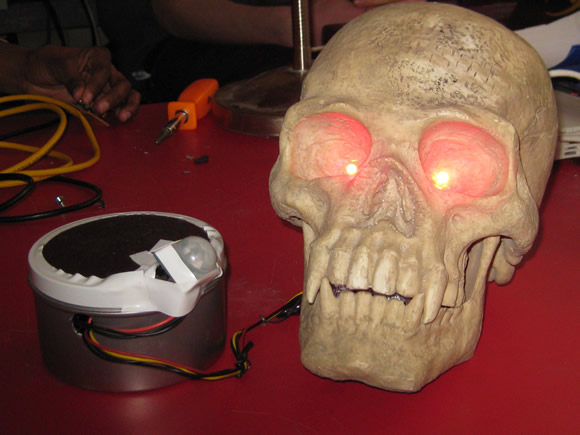
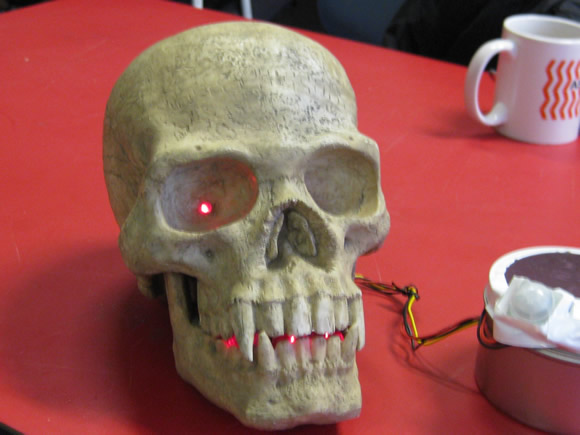
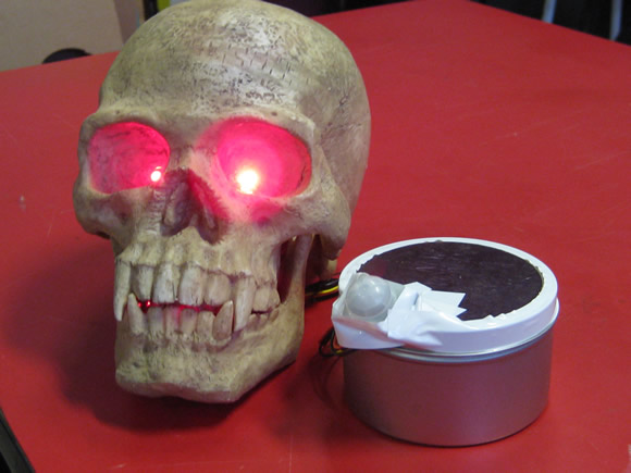
I am ready for Halloween early this year. For my I/O sensor project for Fab Academy I put together a Arduino-controlled motion sensing glowing skull. When motion is detected by the parallax motion sensor, the board turns on the LEDs in the mouth and fades in and out the LEDs glued into the eye sockets.

The Fab Academy Assignment

  • Interface an input device with an output device.

The Project: Motion Sensing Glowing Skull

Voodoo Glow SkullVoodoo Glow Skull

Parts List:

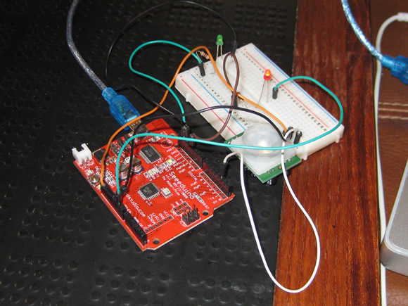
  • 1 Parallax PIR [Pyroelectric (“Passive”) InfraRed)] motion sensor
  • A few lengths of wire
  • 1 Arduino compatible board (I used a Seeduino (Seeed Studios) I had laying around). I like this board because I can flip the power source switch to turn it off / on.
  • 1 9 volt battery
  • Mouth: 10mm Red LED (3)
  • Eyes: 5mm Red Wide-Angle LED (2)
  • 5 in or so metal strip with holes (to house mouth LEDs
  • 3 plastic LED holders (to insulate the mouth LED wires from the metal strip)
  • super glue / hot glue

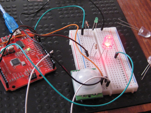
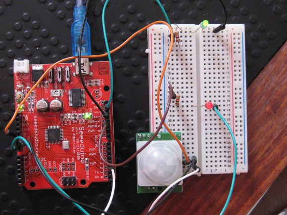
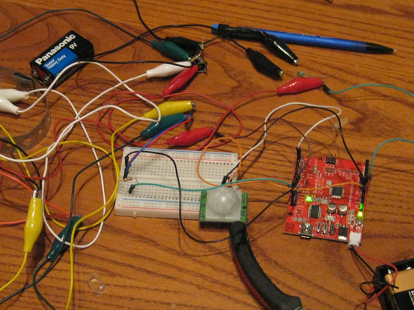
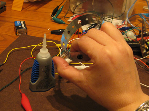
Prototyping the Circuit / Interaction + Putting It Together:

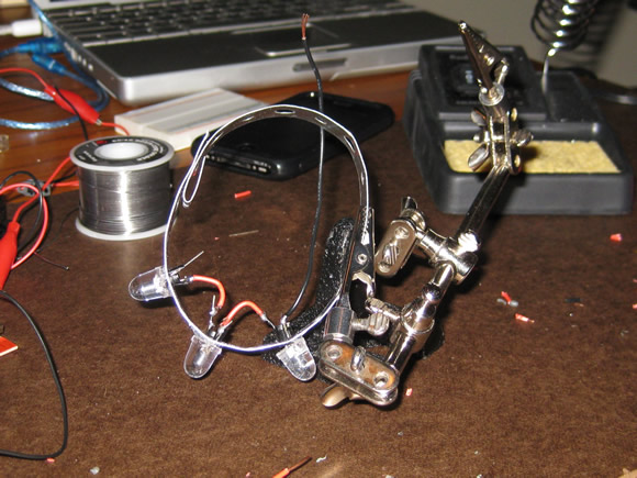
prototypingprototyping - jumbo LEDprototypingprototypingLED harnessLED harnessGlow!

Code:

The code works – but needs to be modified, right now after the motion is activated, the lights stay on / fade in and out in an infinite loop until the power is switched off. Look for an update to this post.

Arduino code for the LEDs and Parallax PIR Motion Sensor:

/* -----------------------------------------------------------------
 Anna Kaziunas France
 --------------------------------------------------------------------
 Fab Academy - Sensors I/O Module
 Glowing Skull Project
 03/02/2010
 --------------------------------------------------------------------
 Motion Sensor code:
 Motion Sensor code:I have seen this code a few places,
 it is never attributed to anyone in particular.
 I saw it last at: http://www.ladyada.net/learn/sensors/pir.html
 --------------------------------------------------------------------
 LED Fader code by: By David A. Mellis - Created 1 Nov 2008
 Modified 17 June 2009: By Tom Igoe
 http://arduino.cc/en/Tutorial/Fading
 --------------------------------------------------------------------
 Combined / Modified by Anna Kaziunas France - 03 March 2010
 --------------------------------------------------------------------

 --------------------------------------------------------------------
 Purpose of this Program
 --------------------------------------------------------------------
 Read input value from the sensor
 Determine if motion is present (input is HIGH)

 When motion is detected via motion sensor:
 1. Eyes slowly glow red (fade in and out - continue)
 2. Mouth glows (steady)

 When motion is not detected after (length of time)
 Switch off LEDs
 ------------------------------------------------------------------*/

// Variables
int ledPinSolid = 13; // choose the pin for the LED
int ledPinFade = 11; //
int inputPinSensor = 2; // choose the input pin (for PIR sensor)
int pirState = LOW; // we start, assuming no motion detected
int val = 0; // variable for reading the pin status

void setup() {
  pinMode(ledPinSolid, OUTPUT); // declare Solid LEDs as output
  pinMode(ledPinFade, OUTPUT); // declare Fader LEDs as output
  pinMode(inputPinSensor, INPUT); // declare sensor as input

  Serial.begin(9600);
}

// Begin Motion Detection
void loop() {
  val = digitalRead(inputPinSensor); // reading input value
  if (val == HIGH) { // if the input is HIGH
    digitalWrite(ledPinSolid, HIGH); // turn LED ON
    // sets the value (range from 0 to 255):
    analogWrite(ledPinFade, HIGH); // turn LED ON
    // fade in from min to max in increments of 5 points:
    for(int fadeValue = 0 ; fadeValue < = 255; fadeValue +=10) {
      // wait for 30 milliseconds to see the fade in effect
      delay(400);
    }
    // fade out from max to min in increments of 5 points:
    for(int fadeValue = 255 ; fadeValue >= 0; fadeValue -=10) {
      // sets the value (range from 0 to 255):
      analogWrite(ledPinFade, fadeValue);
      // wait for 10 milliseconds to see the dimming effect
      delay(110);
    }
    if (pirState == LOW) {
      // we have just turned on
      Serial.println("Motion detected Huzzah!");
      // We only want to print on the output change, not state
      pirState = HIGH;
    }
  }
  else {
    digitalWrite(ledPinFade, LOW); // turn Fader LEDs OFF
    digitalWrite(ledPinSolid, LOW); // turn Solid LEDs OFF
    if (pirState == HIGH) {
      // we have just turned of
      Serial.println("Motion ended");
      // We only want to print on the output change, not state
      pirState = LOW;
    }
  }
}

Skills Learned

  • Basic wiring
  • Modifing Arduino code
  • How to read a sensor datasheet

Tools Used

  • Arduino
  • Paralax motion sensor
Categories
07 3D Molding and Casting Fab Academy Providence -Year I - Student Projects Laser Cutting

Completed TARDIS Cast | Working Light

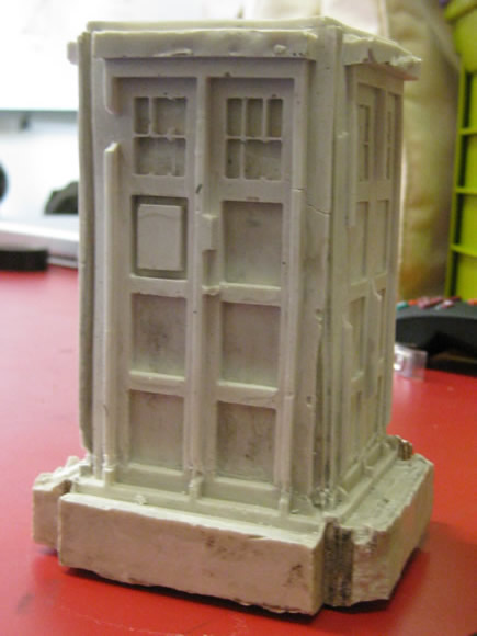
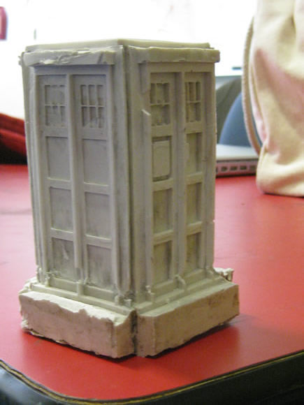
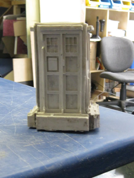
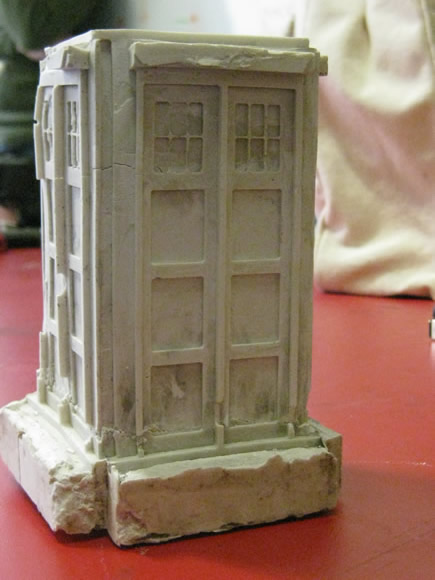
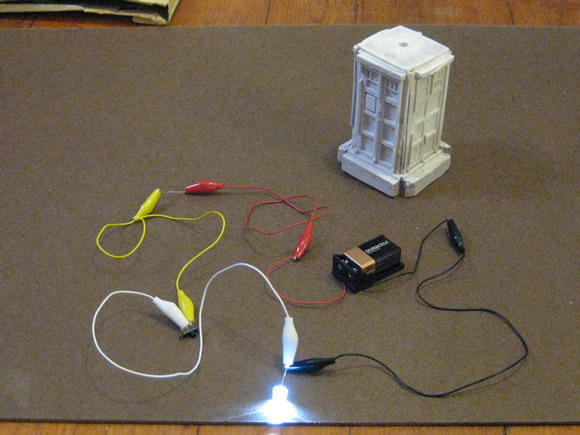
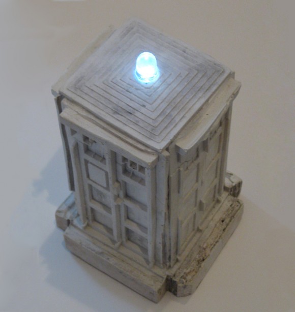
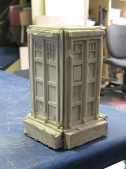
This project went through many adaptations and in the end, it did not turn out as a blue box, but more like a weathered garden statue. The hydrostone did not turn out completely white, but grime on the urethane molds made little swirls, further enhancing the marbleized look. It is not bigger on the inside, but the wiring and battery did fit nicely within the internal cavity. A switch turns it on and off. Although this endeavor did not turn out exactly as planned, I learned many things about thinking in 3D and many more about construction and molding objects in 3D.

So what makes this model a “TARDIS” not just a model of a British police box that looks like a light-up garden statue? Honestly, nothing but my intent. I set out to make a model of the TARDIS and that is what it will be called.
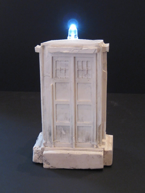
finished model

The process I used to create this model:

Previous Posts:

1. I designed the TARDIS in Google Sketchup.
> See Previous Post: TARDIS: 3D Modeling

2. I used the Modela to mill out the front, 3 individual sides and roof of the model in machinable wax.
> See Previous Post: TARDIS: Moldmaking

3. I used the block of machinable wax to create urethane molds of each of the pieces.
> See Previous Post: TARDIS: Moldmaking

Laser-Cut The Casting Container:

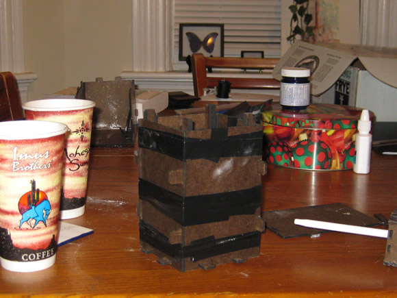
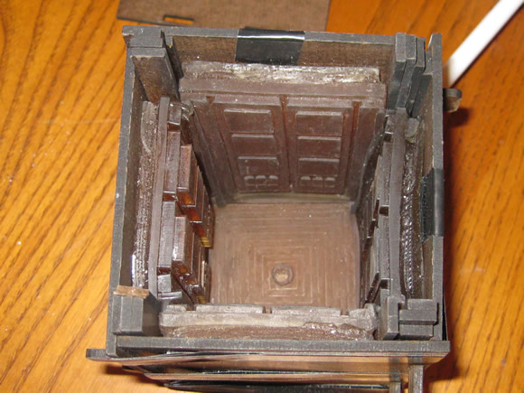
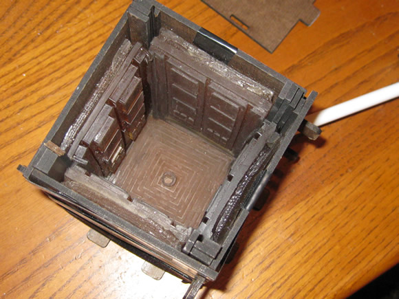
4. I designed and laser cut an adjustable press-fit box to place the individual urethane molds in order to cast the TARDIS in hydrostone. (I also custom-cut shims to key in the urethane mold edges.)
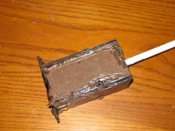
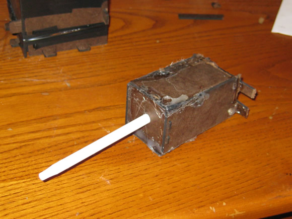
Inside BoxInside BoxTaped Up Boxpreparing to castrubber moldInside Box

Putting Together the Casting Container / Aligning the Mold:

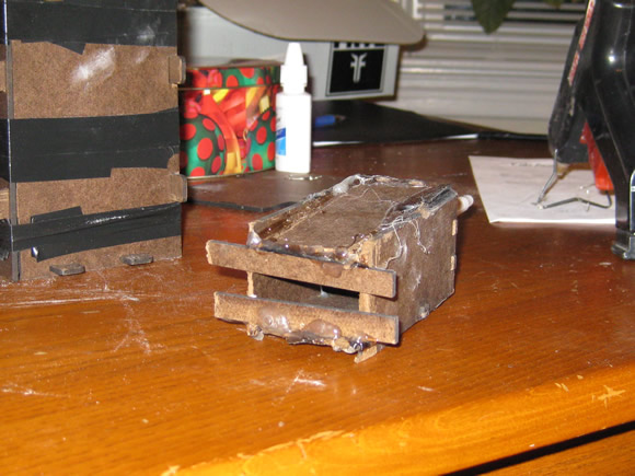
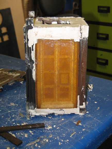
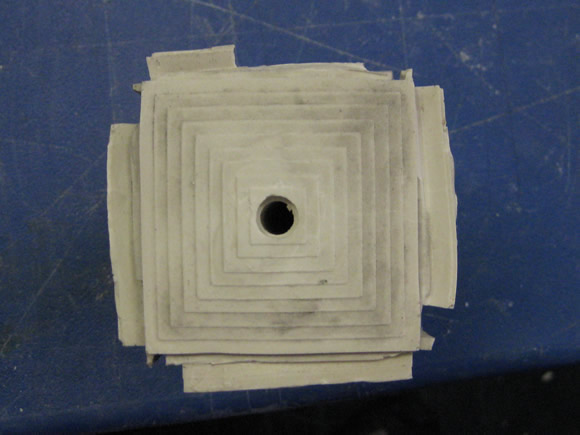
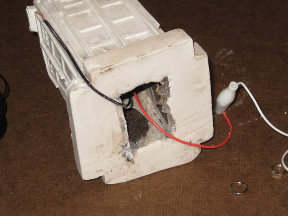
5. When casting, I did my best to align the sides and roof together at the appropriate angles and hoped for the best. An additional laser-cut box with an empty pen casing was inserted into the larger mold when pouring the hydrostone in order to create a cavity for the wires to run form the LED on the top through the cast down into the base where the wiring, battery and other components are housed. The inside box then became part of the cast.
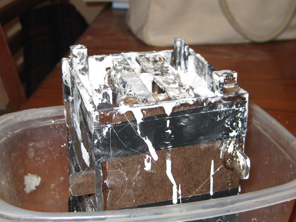
casting

Casttaped up boxremoving box

Removing the Casting Container:

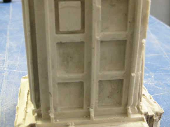
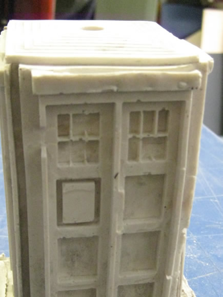
6. When taking apart the mold, I found that some of the fine details of the windows and the moldings became stuck in the urethane mold or broke off easily. I may not have mixed the hydrostone long enough, or there may have been an issue with the proportions I used. Further experimentation is this matter is needed to determine the source of the problem. This breaking away of the fine detail gave the statuette a weathered appearance, like a tombstone left out in the elements.Freshly CastFreshly CastFreshly CastFreshly CastFreshly CastFreshly CastFreshly Cast
Adding the Electrical Components:

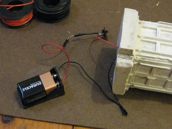
7. In addition – I wanted to have a LED light on the top to simulate the police box light, so when cutting the outside casting box, I cut a congruent interior box (see number 4. pictures above.) This small inside box allows for an open area for the wiring from the LED through the top of the hole in the stone to the battery. The wiring consists of:

  • 1 ultra bright white 10 mm LED
  • 1 330 ohm resistor
  • 1 small switch
  • 1 battery connector and a 9V battery
  • A few lengths of wire

Prototyping the circuit

protyping the circuitprototyping the circuit

I dedicate this project to David Tennant for his the excellent portrayal of the 10th Doctor, which has just come to an end.
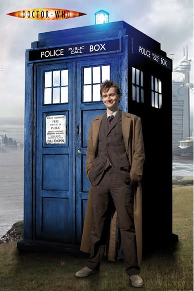
The 10th Doctor and His Tardis
Image © BBC

Categories
07 3D Molding and Casting Fab Academy AS220 - Providence, RI Fab Academy Providence -Year I - Student Projects

TARDIS: Moldmaking

I am still working on my Fab Academy 3D Molding and Casting project (a 3D model and cast of the TARDIS. The implementation of my model proved complicated.

Wax molds with frames

The Fab Academy Assignment

  • Machine a mold and cast parts in it

The Project: TARDIS multi-mold cast

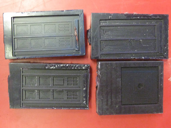
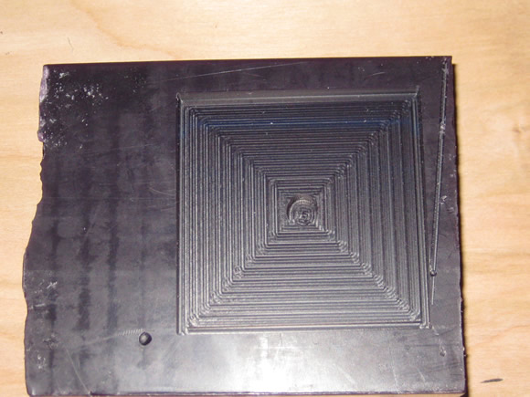
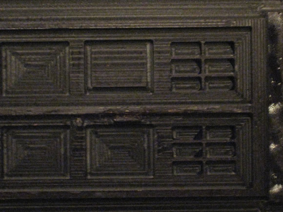
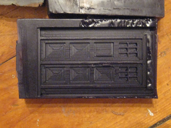
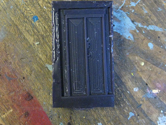
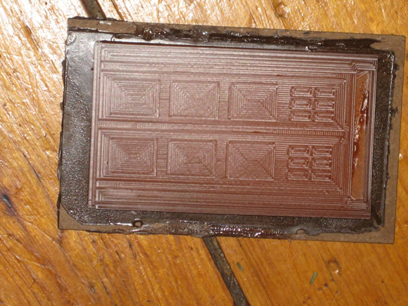
Starting with the cad.py created .rml files (for details on the 3D modeling process see my TARDIS: 3D Modeling post), I carved several molds out a block of machinable wax using the Modela milling machine.

Wax Molds

Wax MoldsWax MoldsWax MoldsWax MoldsWax MoldsWax Molds
Tardis Wax Mold

There were a few mishaps creating these molds. The z-max setting was not high enough on the side mold (you can see where the Modela bit drug through the wax and made lines that were not part of the design.). I learned that it pays to set the z-max close to the max of 1 so that it will clear the edges of the design. However, because this particular design took so long to mill out , 7 hours or so, I opted not to redo it if the damage was minor. Instead, I attempted to repair the damaged areas with wax.

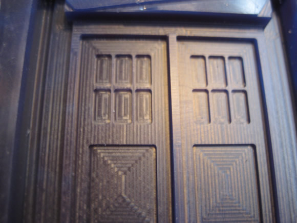
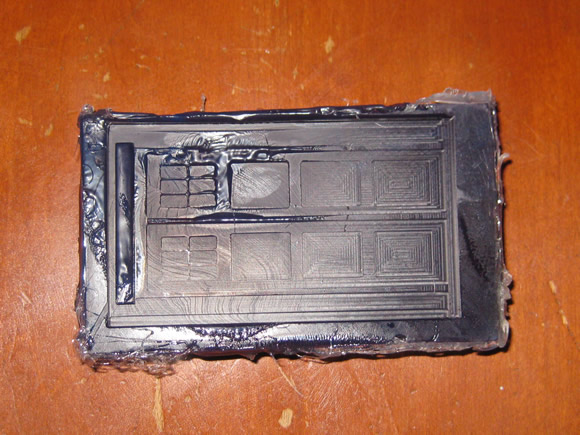
After I made the wax molds, I made casts of each side and the roof using urethane rubber. The door was cast once, but the side needed to be cast 3 times to create the 3D object.

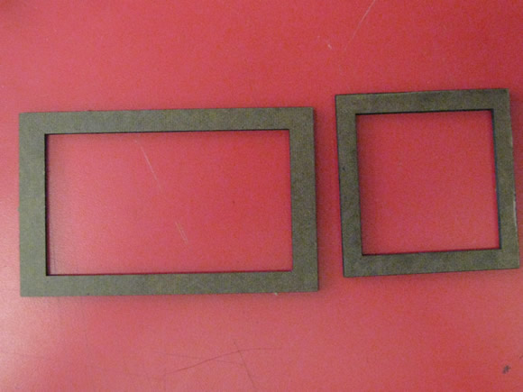
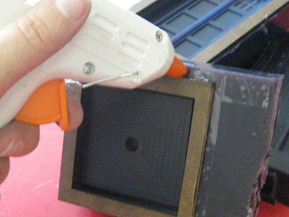
I did not allow for space at the top of the wax molds, so to ensure that the rubber would have enough room to capture the top of the design, I laser-cut some tempered masonite frames in to increase the vertical space for the rubber to fill. These frames also make it a little easier to get the rubber out of the mold.

Creating and Gluing the Frames

cut framesframes

Mixing Urethane / Creating the Molds

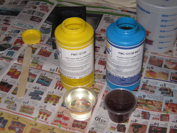
At Fab Academy Providence, we used a smooth-on 2 part urethane mold mix. Just mix equal parts of each container (A and B) and mix slowly in a figure eight pattern to minimize the bubbles.
Rubber MoldsRubber MoldsRubber Molds

What I learned about this material:

  • Mix very thoroughly. Take your time (at least 10 – 15 minutes if you can stand it). The end result will be sticky if the parts are not mixed together well – My first two molds were sticky.)
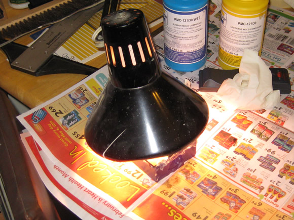
  • Add heat. Heat both accelerates the process and creates a less sticky end product. I used a desk lamp positioned in close proximity to the freshly poured mold.
  • Be careful not to leave the heat on longer than 15 minutes or so and let the wax and rubber cool before removing the rubber mold from the wax.
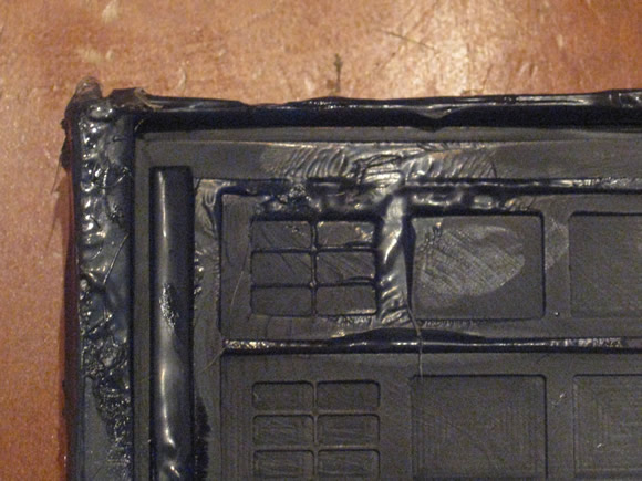
  • I learned the heat lesson the hard way when my mold melted from excessive heat. (see photos below)

Beware of Melting Molds

melted moldmelted mold

All The Molds (Good and Bad)

all molds

Skills Learned

Tools Used

Next Steps:

  • Create a box and system for keying in the sides of the police box so it can be cast.
  • Get LED, resistor and battery to wire up the light on the top.
  • Cast in hydrastone